POINT (Command)
Command description
Points objects can act as nodes to which you can snap objects. You can specify 2D and 3D locations for a point. The current elevation is assumed if you omit the Z coordinate value. The PDMODE and PDSIZE system variables control the appearance of point objects.
You can use MEASURE and DIVIDE to create points along an object. Use PTYPE to specify point size and styles.
Command prompts
Specify a point
Specifies the location of the point object.
Find the command
Ribbon – Home(TAB) – Draw(PANEL)

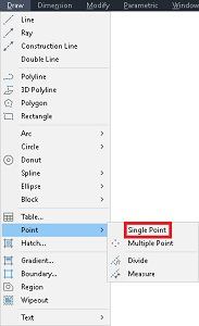
Menu – Draw(TAB)

Draw(TOOLBAR)
Command line type “point”
At the command line you can type the word ‘point’
Alias type “po”
Just typing the letters ‘po’ will also start the line command
Grips

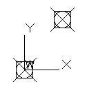
As you see in this image by itself a point can be difficult to see (arrow), until it is highlighted. A point has just a single grip and is associated with the “node” osnap type.
When grip editing the grip will allow you to change its position, it’s also worth pointing out that when you make it a hotgrip the normal method of pressing the spacebar to cycle through various editing options will also let you
**STRETCH** **MOVE** **ROTATE** **SCALE ** or **MIRROR**
Which is a bit pointless really ;>). But joking aside if you change the point style you can see that the point will actually rotate.
Editing
You can directly change a point’s placement by using grip editing, on it’s own a point is difficult to see so using ‘PTYPE’ and ‘PDSIZE’ to make them more visible is a valuable option. (Both of these apply to all points in a drawing, you can’t adjust these values for individual points).
Properties
The following properties are displayed in the properties palette when a point is selected.
General
· Color
· Layer
· Linetype
· Linetype scale
· Plot style
· Lineweight
· Transparency
· Hyperlink
· Thickness
Geometry
· Position X
· Position Y
· Position Z
List properties
When using the List command the following properties are noted.

This can have additional information if the properties of a point are edited so you can also have the information for
- Color
- Linetype
- Linetype scale
- Plot style
- Lineweight
- Transparency
- Hyperlink
- Thickness
if these have been changed from the default values. Again many of these look pointless but they are valid.
Variables
The following is a list of the variables that are relevant to points.
- Elevation
- Lastpoint
- Thickness
- Pdmode
- Pdsize
Script example
Read the section on creating scripts for full details on how scripts work in Autocad, the following is an example for using the point command in a script
——script start——
[membership level=”0,1″]
[/membership]
[membership level=”2,3″]
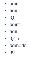
point
non
0,0
point
non
3,4,5
pdmode
99
[/membership]
——script end——
Description
 This short script file will draw two points, the first is drawn on the UCS plane and the second with an elevation of 5 units.. Make sure there are no extra spaces at the end of lines in a script.
Before entering coordinates you should always use the command modifier ‘non’ to stop Autocad snapping to osnap points, this subject is covered in the scripting section but it is always a good idea to do this before every single set of coordinates in a script as it is only valid for one point at a time.
[membership level=”0,1″]
[/membership]
[membership level=”3″]
[/membership]
[membership level=”1,2,3″]
Read the section on creating scripts for full details on how scripts work in Autocad, the following is an example for using the line command in a script
——script start——
- line
- non
- 0,0
- non
- 10,10
- line
- non
- 0,10
- non
- 10,0
- line
- non
- 0,0,5
- non
- 0,10,5
- non
- 10,10,5
- non
- 10,0,5
- c
——script end——
Description (video might be better)
This short script file will draw a square with diagonal lines across the corners. Make sure there are no extra spaces at the end of lines in a script, and a blank line is totally empty (no spaces).
Before entering coordinates you should always use the command modifier ‘non’ to stop Autocad snapping to osnap points, this subject is covered in the scripting section but it is always a good idea to do this before every single set of coordinates in a script as it is only valid for one point at a time.
- line ;this starts the line command, even though this is a script Autocad behaves as though you were entering the commands at the command line and it issues the prompts
- non ;command modifier, temporarily overrides osnap settings so NONe are selectable
- 0,0 ;this is the start point of the line – bottom left corner
- non
- 10,10 ;this is the next point of the line – top right corner
- ;a blank line is used to finish the line command
- line ;start a new line
- non
- 0,10 ;start point of the line – top left corner
- non
- 10,0 ;next point of the line – bottom right
- ;a blank line is used to finish the line command
- line ;start a new line
- non
- 0,0,5 ;start point of the line – bottom left corner (with a Z height of 5 units)
- non
- 0,10,5 ;next point of the line – top left corner
- non
- 10,10,5 ;next point of the line – top right corner
- non
- 10,0,5 ;next point of the line – bottom right corner
- c ;the ‘c’ tells Autocad to close the line back to the starting point used at the start of the command and finishes the line command – back to bottom left corner
[/membership]
Macro example
This short macro will draw a square with diagonal lines across the corners. Make sure there are no extra spaces Autocad treats a space the same as a semicolon and see’s them the same as using the key.
Before entering coordinates you should always use the command modifier ‘non’ to stop Autocad snapping to osnap points, this subject is covered in the macro section but it is always a good idea to do this before every single set of coordinates in a macro.
[membership level=”0,1″]
[/membership]
[membership level=”2,3″]
^C^C^Cpoint;non;0,0;point;non;3,4,5;pdmode;99;
[/membership]
3D
A point is free of any 3D issues, it doesn’t rely on the current UCS settings unlike some other types of geometry that are required to be on or parallel to the current UCS. A point can be placed anywhere in 3D space just by using 3D coordinates when you create it. You will often find points used for marking references, it is also used in georeferencing, point clouds, etc
As a drawing element it is difficult to see unless you alter it’s appearance with the ‘ptype’ command or ‘pdmode’ variable. One really useful way to utilize points is from within the ‘measure’ or ‘divide’ commands, both of these will place point objects along the selected geometry.
The only way that a point is linked to the UCS is when you give it a thickness, a point is thickened in the Z direction that was in operation when the point was originally created, you will see this referd to as the “normal” in some programs. By placing multiple points at the same place in 3D but using different UCS settings, and then adjust the thickness of the points, will give the appearance of a “star”.


