3D Navigation
Description
Even in a 3D model your computer screen still only gives a flat image, still, it is really helpful to be able to view a model from varying angles to be able to visualize how things ‘fit’ together. Full Autocad has the navigation cube to make it easier for you to get around in a 3D model, but that feature isn’t available in LT. We do have the view command (see commands below), as well as the ability to alter the ucs so we can draw on different planes.
To see how to navigate in 3D using LT, scroll down to the 3D section for an explanation by example.
![]() As an LT user you probably are used to seeing this image. Its the UCS icon and it tells you which direction is X and which is Y (the W tells you that this is the World UCS)
As an LT user you probably are used to seeing this image. Its the UCS icon and it tells you which direction is X and which is Y (the W tells you that this is the World UCS)
![]() Depending on your settings you might also have different colors for the X and the Y axis.
Depending on your settings you might also have different colors for the X and the Y axis.
![]() The ‘ucsicon’ command controls how and where the icon appears, and selecting the Properties option opens a dialogue box that affects how the uscicon looks.
The ‘ucsicon’ command controls how and where the icon appears, and selecting the Properties option opens a dialogue box that affects how the uscicon looks.
Choosing 2D or 3D style will let you see the Z axis. And unticking the ‘Apply single color’ shows each axis in a separate color. Take a look at the ‘commands’ section below to see how to use the UCS in 3D.
Grips
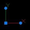 The ‘ucs’ command will let you move the UCS origin by picking a point, and change the angle of any of the 3 axis.
But if you click with the mouse on the UCS, it will also display grips. The square grip at the centre will let you drag the UCS and snap it to any existing osnap points in your drawing, and then the circular grips at the end of each axis allow you to rotate the axis to align with drawing geometry, which is great if you need to use the orthogonal control for drawings at odd rotation angles.
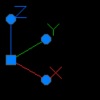 And in a 3D view this works just as easily letting you drag the Z axis to align with existing objects.
Commands
Various commands let you work more effectively in a 3D model. How you can navigate in 3D with these commands is covered below. Look at the command description pages themselves for full details on all the available options. This section only covers the parts you will use for 3D navigation.
ucs
The UCS won’t directly allow you to move around in model space or change the view, but it will let you set the drawing XY plane when it comes to adding drawing objects. And combined with the ‘Plan’ command you can change views of a 3D model.
What the ucs command allows you to do is change the drawing plane in model space, many commands in Autocad will only work on or parallel to the drawing plane, the best way to see this plane is to turn on the grid and set your drawing limits to be small enough to just cover the area you are using, and then using the grid command change the settings to show the grid just for the drawing limits
view
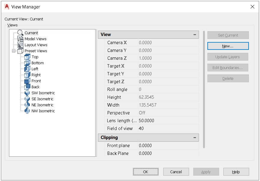 The view command is how you can get about in a 3D model. The default is a dialogue box which will let you choose one of the Autocad preset views. You can also choose to add new views but you will first need to setup that view using -vpoint and then you can save it as a new named view here.
plan
The UCS is used for setting the current drawing plane, most geometry types in LT are limited to be drawn on (or parallel to) the current UCS. Setting the USC so it is aligned to a preset orthographic plane, front, back, front, back, left, right, is a quick and simple way to set the drawing plane you wish to use. With the use of the UCS grips or setting the axis rotation angle, you can make the drawing plane in any orientation you want.
vpoint
The vpoint command is used to tell Autocad which exact point in 3D space you wish to look from, and your view of the model is rotated to view the o,o,o point of the current UCS from this point in space.
Imagine you are placing or holding a camera, it will always be pointing at 0,0,0 (there is no way in LT to move the TARGET point, but you can change the UCS origin to be the current 0,0,0 point) and you can place this camera anywhere you want in the surrounding model space.
The vpoint command has a few methods of working, by default you open a dialogue box where you can choose whether the viewpoint is based on the world UCS or the current UCS, and you can visually pick an angle around the central target point in the XY plane, and then you can pick an angle above or below this plane. There is also the option to reset everything back to the standard plan view with the ‘Set to Plan View’ button.
Starting the command line version ‘-vpoint’ gives you some more options, firstly the default when you press ‘Enter’ is to open a live camera and tripod preview unfortunately this doesn’t actually show your model which would make it really usefull, it only shows the UCS orientation, but once you get used to what it is representing then it can be handy.
WIth Dynamic input turned on you can enter 3D coordinates in the form 1,1,1 (comma separated) to tell Autocad where the view from point will be. And the view automatically changes zooming to extents.
You also have the option to choose the rotation values (click the down arrow or type “r”), this will let you enter the rotation angle on the XY plane followed by the rotation angle from the XY plane, the same as you would in the vpoint dialogue, but just using keyboard input (also good for scripts and macros).
Variables
The following is a list of the variables that can have an effect on 3D content
- Elevation
- Thickness
- ucsfollow
Script example
Read the section on creating scripts for full details on how scripts work in Autocad, the following is an example for navigating around a model in a script, using the ‘-vp’ (-vpoint) command along with ‘hi’ (hide), the ‘delay’ (2000 milliseconds or 2 seconds) is used to slow the whole thing down or it would happen just too quickly for you to see. This also is the very basics for creating animated sequences in LT.
——script start——
- -vp
- -0.14,-1,.5
- hi
- delay
- 2000
- -vp
- 0.42,-.91,.55
- hi
- delay
- 2000
- -vp
- 0.84,-.54,.6
- hi
- delay
- 2000
- -vp
- 1,0,.65
- hi
- delay
- 2000
- -vp
- 0.84,0.54,.7
- hi
- delay
- 2000
- -vp
- 0.42,0.91,.75
- hi
- delay
- 2000
- -vp
- -0.14,1,.7
- hi
- delay
- 2000
- -vp
- -0.65,0.76,.65
- hi
- delay
- 2000
- -vp
- -1,0.28,.6
- hi
- delay
- 2000
- -vp
- -1,-0.28,.55
- hi
- delay
- 2000
- -vp
- -0.65,-0.76,.5
- hi
——script end——
The script above is a cut down version of the one used to create this animation.
Macro example
This short macro will draw a square with diagonal lines across the corners. Make sure there are no extra spaces Autocad treats a space the same as a semicolon and see’s them the same as using the <ENTER> key.
Before entering coordinates you should always use the command modifier ‘non’ to stop Autocad snapping to osnap points, this subject is covered in the macro section but it is always a good idea to do this before every single set of coordinates in a macro.
^C^C^Cline;0,0;10,10;;line;0,10;10,0;;line;non;0,0,5;0,10,5;10,10,5;10,0,5;c;
3D
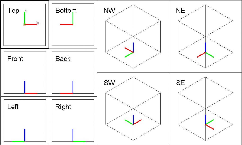
To show you how these commands above can be used it would be best with an example of a 3D object, let’s take an LT wireframe cube, that measures one unit by one unit by one unit, I’ve prepared a drawing with 10 viewports to show each orthogonal and each isometric view of the cube. And labelled them according to the standard Autocad views.
- Top
- Bottom
- Front
- Back
- Left
- Right
- NW
- NE
- SW
- SE
Can you see how utterly confusing this is? If you highlight a viewport (Top) then the UCS becomes visible making it a little easier to work out which way is up etc. in all the different views (but not much). In Autocad the UCS is only visible in the active viewport, I have drawn the colored lines to make it more visual. This is something you will just have to learn to interpret though in most models I would imagine it would be easier to ‘see’ where you are.
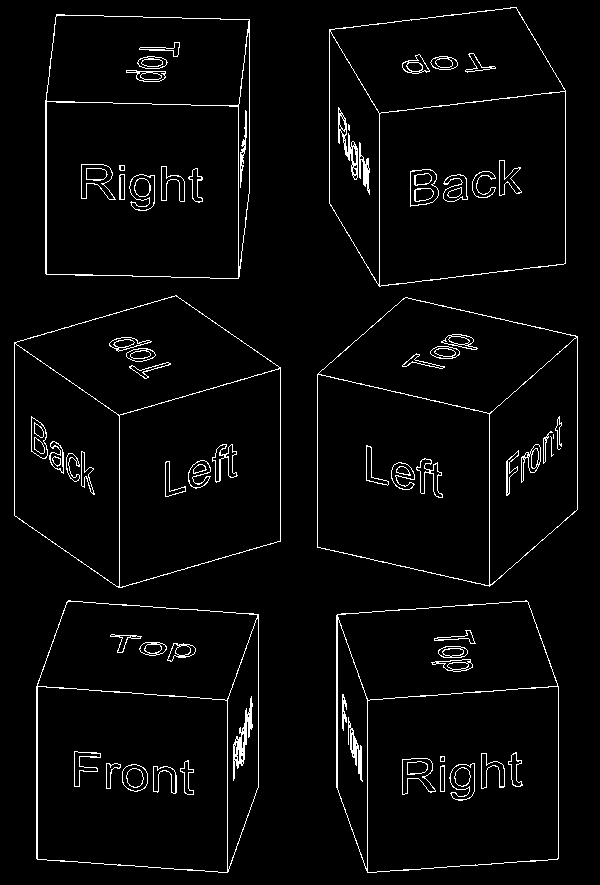
Changing the objects that make up the cube so that it will work with hidden line removal and adding text to each face makes visualization a lot simpler. Here is the same cube but drawn using regions so that the ‘hide’ command can be used. Do you notice that the colored UCS lines are only visible in the bottom view, that is because I actually drew them as lines and it isn’t the built-in ucs icon, and so in a hidden view they are mostly lost, the base of the cube is centred at 0,0,0 the same as the UCS, that’s why you can see it at the bottom of several views.
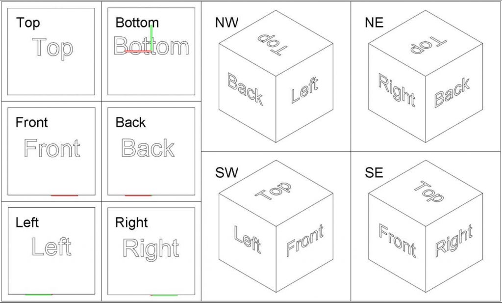
This is one of the problems you will face using LT for working in 3D, without a navigation cube visible on the screen you have to rely on getting your orientation just from the UCS, which at times can be a little difficult. Another drawback is that the ‘hide’ command freezes the Autocad pan and zoom with the mouse, you can draw, but to be able to pan or zoom you first need to run the ‘regen’ command which switches you back to a wireframe view. Read the page on geometry for hidden lines to see ways around this.

